
IT'S ALIVE!
I finally got the pieces together and assembled the components onto the main board of the impedance tester project.
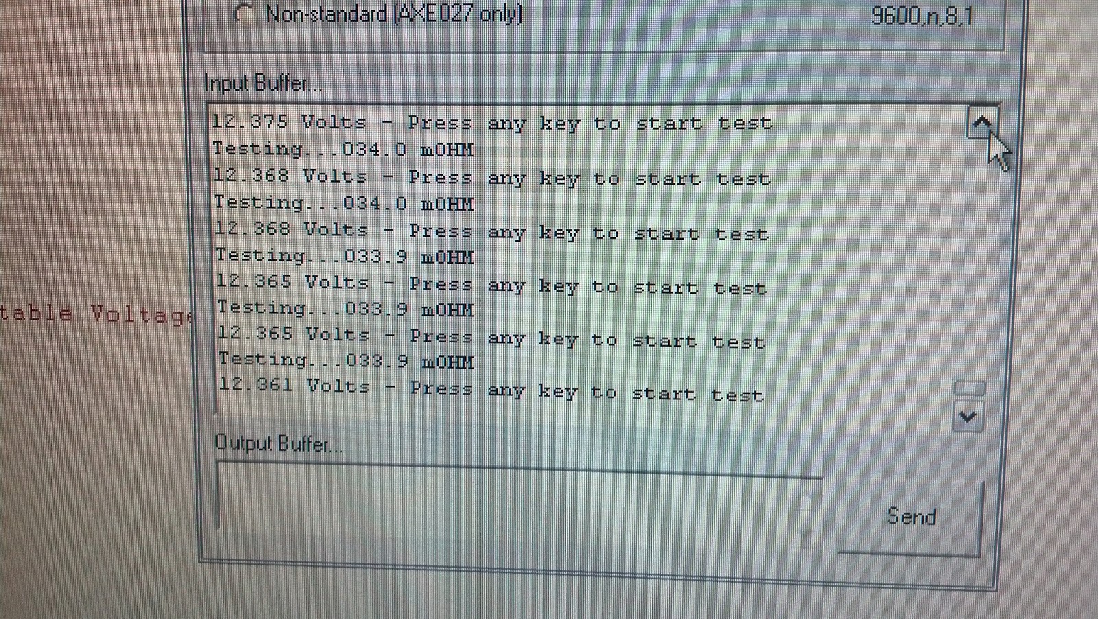
I did some initial testing of each AD circuit (MCP3202 12-bit for voltage and ACS713 hall sensor for current) and then the FET on/off test. Everything worked perfectly! So I've got some very beta code going using the terminal as the UI. Looks good so far! I am getting consistent results within +/- .3 milliOhms so I am very pleased! I am cycling ~10 amps of load (~1.2 Ohm resistance) and using a kelvin style hookup to keep the load current from interfering with the voltage sense at the cell/battery. I need extreme accuracy and a sensing resolution of .001 volts in order to get a valid internal resistance measurement. As always leave a comment if you want me to post the code.


' Program By Michael Bentley.
#picaxe 20x2
#Terminal 9600
#No_Table
#No_Data
#freq m4
Symbol ADVal = W0
Symbol Channel = B2
Symbol Q = B3
Symbol Config = B4
Symbol AMP = W3
Symbol V1 = W4
Symbol V2 = W5
Symbol V3 = W15
Symbol V4 = W12
Symbol U = B12
Symbol W = B13
Symbol X = B14
Symbol Y = B15
Symbol Z = B16
Symbol VOLT = W10
Symbol VOLTSTART = W11
Symbol IMP = W13
Symbol IMP2 = W14
Symbol FET = C.5
Symbol SCK = B.7
Symbol CS = B.0
HSPISetup spimode00, spimedium
Low SCK
High CS
Pause 500
SerTxD ("Impedance Tester", CR, LF, LF, "by Michael A. Bentley",CR, LF, LF)
Main:
Do
pause 500
Channel = 0
GoSub ADMeas
VOLTSTART = ADVal
V1 = ADVal * 3
V2 = ADVal * 5/10
'V3 = ADVal * 0/100
V4 = ADVal *5/1000
VOLT = V1+V2+V4
BINTOASCII VOLT,U,W,X,Y,Z
SerTxD (U,W,".",X,Y,Z," Volts - Press any key to start test",CR,LF)
SerRxD [3000,Main],Z
IF VOLTSTART > 275 then Goto Test
Loop
Test:
serTXD ("Testing...")
V1 = VOLTSTART - 275
high FET
for X = 0 to 255
channel = 0
gosub ADMeas
if ADVal < V1 then
low FET
SerTxD ("ABORT-Unstable Voltage!")
goto Main
endif
pause 12
next X
pause 50
readadc10 B.1, AMP
AMP = AMP - 103
Channel = 0
GoSub ADMeas
V1 =ADVal
pause 10
low FET
pause 100
Channel = 0
GoSub ADMeas
ADVal = ADVal - V1
V1 = ADVal * 3 * 10
V2 = ADVal * 5
V3 = ADVal * 0/10
V4 = ADVal * 5/100
VOLT = V1+V2+V3+V4
VOLT = VOLT *10
V1 = AMP * 2
V2 = AMP * 6/10
V3 = AMP * 4/100
AMP = V1 + V2 + V3
IMP = VOLT/AMP * 10
IMP2 = VOLT//AMP *10 /AMP
IMP = IMP +IMP2
BINTOASCII IMP,U,W,X,Y,Z
SerTxD (LF,W,X,Y,".",Z," mOHM", CR, LF, LF)
pause 500
Goto Main
ADMeas:
low B.0
hspiout (001101) ' CH0
hspiin (b1,b0)
high B.0
w0=w0/8
Return
Hi Mike,
ReplyDeleteI'm also using the 713 in a project with a PIC.
The problem is to calculate the scaling factor for the 713 output, from ADC raw data to actual current.
What's the trick?
thanks!
Frank.
So I'm using the 185mV/A version of the 713. If my Picaxe is running at 5.0 volts and so is the 713, then when I read the AD channel at 10 bits we get 5.0/1023 which equal .0048875 volts per tick. Now we have to compensate for the output of the acs713 has (5.0 x .1) .5 volts added to the output signal. So .5/.0048875=102.3. So we subtract 102 from the reading first. This gives us our raw value in what I call ticks. We take this and multiply by .0048875 and get our Voltage equivalent. For example We read 478 from the port and subtracted 102 and we get 376. Then we multiply 376 by .0048875 volts per tick to get 1.8377 Volts. Now we have the voltage output from the ACS minus the .5 offset already so we take 1.8377 Volts and divide it by .185 (185mV) and we get 9.9335 Amps. Tada! Now we can make this even easier. We know now that the output of 376 ticks gives us 9.9335 Amps so we can just figure 9.9335/376 gives us .0264 Amps per tick. So this simplifies our math in the program. Just take the raw reading, subtract 102 and multiply by .0264. Now doing this on a Picaxe takes some severe wrangling as it only supports 16 bit integer math so you have to jump through hoops and you can see in my program which I have now pasted to the bottom of the post. Hope this helps!
Delete