Wednesday, August 20, 2014

Baby Reminder prototype


Some quick pics of a prototype I have been working on. It reminds you to check if you have a baby onboard when the car engine is turned off by playing a lullaby tune. It works on power ports that turn off or stay on when the key is removed by sensing voltage levels and auto calibrating to your vehicle. The green led turns on when the unit is armed and working. When the engine is turned off, after a delay of 2.5 seconds the green led turns off and the tune is played. I'm still tweaking the program parameters.

Thursday, July 24, 2014

Picaxe 20M2 cheat sheet

I just finished making a cheat sheet for my favorite Picaxe chip, the 20M2. I figured I would share it here for those interested. It is posted on the Picaxe forum website so you need to be a member to get it I think.

Picaxe 20M2 Cheat Sheet


Wednesday, October 16, 2013

New Workbench!


     I just finished building my new electronics lab workbench downstairs in the basement. I really like it. I used the 2x4 Basics kit from Amazon.com which lets you easily create a custom workbench using only 2x4's and plywood sheets. I used a high quality finished oak 3/4" plywood for the top. The basement is unfinished and a bit dingy so I decided to make the bench enclosed. It is 6 feet wide and 3 feet deep. I also installed a True-HEPA air purifier which creates a positive pressure inside the benchtop area, especially when it is closed up. I am trying to achieve an equivalent of an ISO 6 or Class 1000 clean space. I want it clean so I don't get any dust buildup on my parts and test instruments. I'm also looking to do some vacuum chamber experiments with metal film deposition and I need clean air for my 2 stage rotary oil sealed vacuum pump. I just need a Bell Jar and test stand now...

Wednesday, August 28, 2013

Impedance Tester alpha build


IT'S ALIVE!

 I finally got the pieces together and assembled the components onto the main board of the impedance tester project.

Saturday, August 25, 2012

Shocker!


WARNING!!! High voltages present! Use caution!

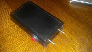
My son asked me a while ago if we could build a device that would shock people. I said "why not" and drew up this little circuit. We then cobbled it together from some pieces I already had. This is not a debilitating device, it just gives a potent "what the heck!" kind of shock. It has a peak impulse of +1250V when the field in the transformer collapses and I am pulsing at 1000Hz. I checked the maximum current draw with the secondary shorted and measured 4.7milliamps so it is under the "heart safe" 5 milliamp limit. The driver is a Picaxe 08M. The first test was disappointing because the frequency was low and timing of the magnetic field setup and collapse was off. I could just hold the wires and feel the pulses.Once I got the timing tweaked using an o-scope by changing the code in the micro, watch out! This sucka bites! I also had to remove the diode across the transformer as it was absorbing the field collapse impulse which turned out to be much stronger than the setup inrush voltage pulse. Go figure, I should have known this given the time to setup the field from the apparent high impedance source of the battery on the primary was longer than the field collapse rate on the secondary and all that energy over time was being released much faster during the field collapse.

WARNING: Potentially hazardous voltages may be present within this circuit.Clicking read more will allow you to see the inside pictures and schematic. If you decide to build this circuit please be careful and responsible. You are responsible as the creator of the device for it's proper use and operation. If you are under 18 you MUST consult with your parent/guardian before building this project. Failure to do so will result in suspension of hobbyist activities and banishment from the lab!

Friday, August 24, 2012

PCB arrival


Hooray! My new custom circuit boards for my battery impedance tester project just arrived. Now I can start assembling a prototype and get some code going on the micro (Picaxe 20X2). I should be able to achieve 350 micro-ohm resolution, which should be good as most of the batteries I intend to test are 4000 uOhms and greater when new. This should give me a good idea of the battery health. I intend to cycle the 1 Ohm load across the battery and measure the voltage drop with the 12-bit ADC. I haven't decided if I'm going to ramp it up PWM style or just switch it on, read voltage, then back off. I will have to try both ways and see what works best.

Battery Charger - PWM controlled.


This is my latest project I just completed. It is a multi-channel lead acid battery charger. It can be used for VRLA, gell cell and wet cell types. It is designed to charge battery jars with a nominal voltage between 4 and 12 volts. It will also work well with any battery type requiring a constant voltage float charge. It has built in limiting circuitry to keep each channel at or below 1.25 amps. The individual channels may be paralleled for higher current. Once the set voltage is adjusted and the channel is turned on, the charger will try to drive to the set voltage while automatically current limiting. As the set voltage is reached the current diminishes to a fractional amount that is required to "float" the battery at that setpoint. The system has automatic fault detection for over/undervoltage and battery disconnect as well as open cell detection and will automatically turn off the affected channel.

USB Charger

Here is my USB charger that I made about 1.5 years ago. It has a bit of wear and tear on it but is still holding up. It can output over an amp of current to any USB chargeable device. The display shows voltage and current draw. It shuts off after 60 seconds automatically if no current is drawn. The screen is a .96" OLED and that is a 6V solar cell on top so it charges itself just by laying around, preferably in the sun. It has 6000 mAh of Li-poly onboard and can be charged by either solar, mini-usb or DC 6V input. It uses an LV-
BOOST, Allegro ACS713 current monitor, FET and a Picaxe 20X2. The charger board is by Sparkfun.

Sunday, January 22, 2012

Battery Current Alert


Here are a few pics of my battery current alert or BCA. It watches ripple currents induced by the rectifier in a VRLA or other lead acid systems to determine battery health and sets off an alarm if the ripple is too high or too low. It uses a picaxe 14M microprocessor, precision reference, precision rectifier (personal hybrid design using a ZXCT1041- see U1,C1,C2,R7-R9.) The final design replaced the dip switch bank and led shown in the drawing with 2 toggle switches and a buzzer.